Backup for http://www.scielo.br/scielo.php?script=sci_arttext&pid=S1678-58782003000100001.
Journal of the Brazilian Society
of Mechanical Sciences and Engineering
Print ISSN 1678-5878
J. Braz. Soc. Mech. Sci. & Eng. vol.25 no.1 Rio de Janeiro
Jan./Mar. 2003
A. L. MartinsI; F.
M. CatalanoII
IEMBRAER, SŃo Josķ dos
Campos, SP. Brazil. Email: almartins@embraer.com.br
IIAircraft
Laboratory USP-SŃo Carlos, S.P. Brazil. E-mail: catalano@sc.usp.br
ABSTRACT
A direct optimization study was performed to produce a preliminary evaluation of the potential benefits of a mission adaptive wing employing variable camber technology in typical jet transport aircraft missions, in terms of fuel efficiency increase directly obtainable from airfoil viscous drag reduction alone. A 2-D airfoil analysis approach was adopted, associated with an idealized variable camber mechanism based on elastic deformation and surface extension. Using a direct function optimization program coupled to a viscous-inviscid airfoil analysis routine, optimized variable camber configurations were obtained for several weight conditions of a typical transport aircraft along a sub-critical cruise mission leg. Independent runs were executed considering only trailing and both leading and trailing-edge camber variation and, for each of them, an integrated range parameter has been obtained, proportional to the maximum possible aircraft range. Results indicate that the range increases up to 7.03% over the base airfoil that could be reached with camber variation in the trailing edge region only, and up to 24.6% when leading edge adaptation was considered simultaneously. However, pressure distribution results indicate that the high leading-edge curvatures required for that would probably decrease cruise critical Mach. On other hand, the trailing-edge only approach may offer better conditions for supercritical cruise.
Keywords: Mission adaptive wing, optimization, wing aerodynamics, drag reduction
Introduction
Several concepts have been previously proposed to make the idea of real-time aerodynamic shape adaptation of an aircraft a feasible proposal from both technical and economical standpoints. Almost certainly, the mostly studied idea is the use of a Mission Adaptive Wing (MAW), in which wing geometric shape variation is applied to optimize the aircraft's aerodynamic performance for each situation of its flight. Variable sweep wings and even high-lift devices may be seen as MAW concepts in operation today.
Another
widely researched MAW concept is the Variable Camber Wing (VCW), in
which airfoil sections can have their camber line geometry locally
modified, independently and smoothly in both spanwise and chordwise
directions. An early implementation has been seen in the NASA
AFTI/F-111 experimental aircraft (Powers & Webb 1997), where
the
concept has proved to be able to improve cruise and maneuver
performance in typical tactical fighter missions. As noted by Gilyard
and Espa±a (1994) it is expected that any MAW concept would
bring greater benefits for combat than for civilian transport aircraft,
once the latter are designed and optimized considering much less flight
variation along their missions, that is, mostly for high speed
economical cruise. In spite of that, the potential gains of VCW
technology in civilian operations have been seriously considered by
leading manufacturers, due to their potential significance within a
highly competitive market, marked by recession and globalization.
Research work on VCW technology applied to transport aircraft was
extensively reviewed by Fielding and Vaziry-Zanjany (1996a), who
analyzed many previously obtained results against a maintenance and
operation feasibility background. Encouraging operational costs
reductions were obtained for several of the operation environments
modeled.
The
potential benefits of VCW technology in civilian operations have been
pointed out by many authors Szodruch 1985, Fielding et al (1996a), and
McKinnon (1993) such as:
• extended buffet boundaries by up to 15%
• Wing root moments reduction by up 12%
Resulting
in reduction of fuel consumption and structural weight as well as
improved maneuverability and operational flexibility.
Taking
this scenario into account, the present work has been proposed as an
extension of previous research (Martins & Catalano 1996b and
1998b). Its main objective is a preliminary evaluation of the potential
benefits of VCW technology to enhance the fuel efficiency of jet
transport aircraft by wing airfoil viscous (pressure and friction) drag
reduction, at high speed, subsonic cruise flight conditions. Once
defined a VCW airfoil model and other assumptions, the evaluation was
performed by optimizing variable camber parameters for several stages
along a typical transport aircraft mission. The optimization objective
function is set to maximize an integrated airfoil range parameter,
considered to be representative of the maximum possible variation of
aircraft range due to viscous drag reduction.
The Optimization Problem
VCW technology is considered to be useful mostly in the cruise phase, during which a jet transport aircraft spends most of its fuel. In cruise, the aircraft's main source of inefficiency is its own weight reduction due to fuel consumption. Once a fixed geometry wing can be optimally designed for one set of weight and flight conditions only, transport aircraft usually cruise at off-design conditions.
To
evaluate the cruise weight variation effect on range, one must take the
integral form of the range equation (Raymer 1989) for a jet aircraft,
expressed by:
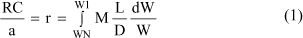

Where R is the aircraft range
(km), C the specific fuel consumption (L/h), a
the speed of sound, W the aircraft weight (N), M
mach number, L/D
lift to drag ratio and the indexes 1 and N indicate conditions at the
start and at the end of the cruise phase, respectively. It is evident
that the maximization of the M(L/D) term at every point of the cruise
leg maximizes the integrated range parameter r.
Based on that, the optimization problem studied here can be stated with
the following enunciate:
Given
a typical jet transport aircraft cruise mission, find the set of
variable camber wing parameters that optimize (maximize) the M(L/D)
term for every weight condition found within the W1
to WN variation range, so maximizing the
integrated range parameter r.
Obviously, the M(L/D) optimization described above should consider the whole aircraft drag variation due to VCW application, which includes, for example, trim, induced and fuselage upsweep drag effects. Nevertheless, the present work considers the optimization of the wing alone, from the standpoint that such results would represent the maximum potential benefits the wing itself would be able to offer in terms of viscous drag reduction, without considering eventual trade-offs with other sources of drag.
Variable Camber Wing Representation Model
It has been decided that a simultaneously simplified and idealized modeling approach would be the most fruitful, for several reasons. A simplified model allows a fast evaluation of numerous conditions and a global vision of the problem, without eventual diversions that could be introduced with a modeling too sophisticated. On the other hand, the model should be representative of the optimization problem, also setting a solid base for future, more advanced analysis. With that in mind, an approach restricted to the two-dimensional airfoil domain has been chosen, representing a basic jet transport aircraft wing by a typical supercritical airfoil, Fig. 1.

The
proposal of a really feasible VCW mechanism is considered far beyond
the scope of this work, and also unnecessary for a preliminary
evaluation. On the other hand a highly idealized mechanism would
represent the outer envelope of possible solutions, that is, many
possible "real world" VCW devices could be seen as some particular
case, covered by the idealized model.
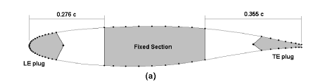
Based on that, the idealized variable camber
mechanism proposed is presented in Fig.
2.
As in previous VCW proposals (Powers 1997, Szodruch 1985, Fielding
1996a, Martins & Catalano 1996b, Campanile 1998a), the
mechanism
assumes a central load carrying fixed section of the wing and two
geometrically variable sections attached to it. Here the variable
sections extend from the LE (leading edge) to 27.6% of the chord and
from 64.5% of the chord to the TE (trailing edge) (Fig.
2a).
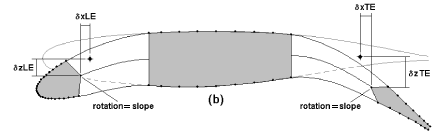
The main idealization assumption for the mechanism is that shape
variation could be entirely achieved by elastic deformation and length
extension of the upper and lower surfaces of the variable sections. For
this, two regions on the variable sections are considered to be
"plugs", fixed in geometric shape to a certain extent of the chord from
the LE and TE (Fig. 2a). It
has been verified
that the original airfoil could be closely reproduced by a single
parametric cubic spline function, interpolating only the points on the
fixed central section and on the LE and TE plugs. Arbitrary shape
variation is then obtained through the following procedure:
arbitrary
displacement (dX, dZ) of LE and TE plugs, measured
from an assumed reference point on each of them ("RP", Fig.2b), where dX,
dZ are displacements in X and Z directions; rotation
of the plugs around the reference points. To keep minimum structural
feasibility of the shape obtained, the rotation is assumed to be the
slope of natural cubic spline curves, attached to the mean camber line
of the central fixed section, and passing through each plug reference
point (Fig. 2b);
resampled
airfoil representation by a single parametric cubic spline function,
interpolating only the points on the LE and TE plugs and on the central
fixed section. Fig. 2c
shows an example resulting airfoil, discretized in 65 points and ready
for aerodynamic analysis (Fig. 2c).


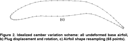
The
cubic spline representation is considered to closely reproduce the
possible shape the flexible variable sections would assume, given a
certain plug displacement and rotation configuration. Also, it is
observed that the airfoil-exposed surface may actually be varied for an
arbitrary displacement. A real mechanism that would possibly behave
this way would be one in which the plugs push and pull flexible skins
into and out of the central fixed section, through slots, while flexing
the surfaces at the same time.
Analysis and Optimization Methods
Given the aerodynamic modeling assumptions, the airfoil analysis method by Williams (1984) was adopted. The method uses an integral boundary layer method, extended to also calculate separated flow by assuming a two-parameter description of the separated velocity profiles. The program is of the semi-inverse type, in which a direct inviscid calculation is coupled to an inverse calculation of the boundary layer. The outer inviscid flow is assumed to be both incompressible and irrotational, so that it can be described by the relevant solution of Laplace's equation, which is obtained by a surface singularity (panel) method. The matching scheme also allow solutions of the potential equations for compressible flow to represent the outer-flow by using linearized small-disturbance compressible flow with Prandt-Glauert coordinate transformation In the inner viscous flow, the laminar portion of the boundary layer is calculated by a compressible version of Thwaites' method and natural transition is predicted using Granville's (1953) correlation. If laminar separation occurs before transition, then the laminar separation bubble is calculated using Horton's (1967) semi-empirical technique. The development of the turbulent boundary layer and wake is calculated by the inverse formulation of Green's lag-entrainment method. To control the overall optimization procedure, the optimizer program CONMIN, by Vanderplaats (1973), was adopted. The program is coupled to the airfoil analysis routine, running it as a multivariable function evaluator. A chosen objective aerodynamic characteristic F (for example, M L/D) is declared dependent of a chosen set of decision variables {Xi} (for example, VCW defining parameters). Using an iterative gradient method, the optimizer is able to numerically search for the set of decision variables values {Xi}opt (opt = optimum) which returns the minimum (or maximum) value of the objective aerodynamic characteristic chosen F({Xi}opt). The final set of decision variables must be constrained to a certain domain by inequality equations, to ensure that the final result is feasible for the conditions required.
Typical Mission Conditions
To define typical cruise mission conditions, general data were obtained from Raymer (1989) for several aircraft, considered to be representative for medium/short range jet transports. The following points deserve detailing:
(a) Atmospheric conditions at cruise were assumed to be those for ISA at 25.000 feet. However, high typical cruise Mach numbers could not be reproduced, due to the flow analysis limitations to subcritical flow, discussed above. Based on preliminary evaluations of the base airfoil (Fig. 2), a reference cruise Mach number of Mref = 0.575 has been assumed, which assures subcritical conditions up to a Lift coefficient CL = 0.65. The Reynolds number is calculated based on a mean aerodynamic chord MAC of 5 m, leading to a value of a Reynolds Number Re = 32 x 106, for the base airfoil, a representative average for jet transport aircraft.
(b)
Supposing a mission where all (non reserve) fuel is used, cruise weight
fractions for that kind of aircraft have a lower limit of about:


This
value was adopted here, once aircraft with larger weight variation will
probably earn more benefits from VCW adaptation ability.
(c) A non-dimensional weight parameter w
has been adopted to express weight whenever needed. Assuming a constant
altitude cruise, weight can be written as:


where w =M2CL,
r the air density (Kg/m3)
and S a reference area (m2). Once the wing
generates most of the lift, the aircraft CL
represents the average section CL
observed at any point across the span. So, for the present 2-D
approach, the most representative choice is to consider the same weight
parameter range (w2 <
w < w1)
for the airfoil alone. Although the complete design of a
three-dimensional wing would obviously take spanwise variations into
account, this assumption is considered representative enough to allow
comparisons between conventional and VCW technologies, which are the
focus of this work.
Numerical Optimization Scheme
Once
the basic modeling, methods and overall optimization conditions were
chosen, a numerical optimization scheme was implemented. A flow diagram
showing the main procedures involved is presented in Fig. 3.
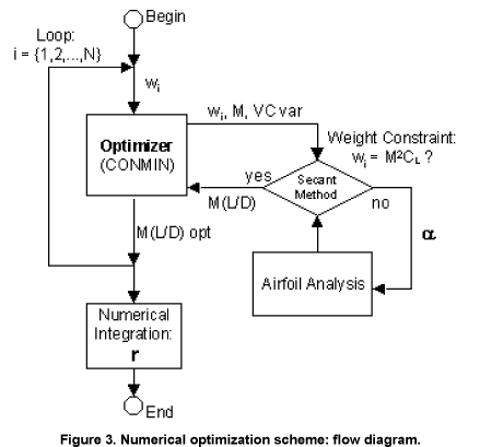
Initially, a discretized representation of weight parameter variation along the cruise mission must be established. The total weight variation interval [w1,wN] is divided into (N-1) equal intervals, defining N different weight conditions wi. For each wi weight parameter value, an optimization run is performed, where program CONMIN maximizes the airfoil M(L/D) parameter, using the airfoil analysis routine to evaluate the effect of the available decision variables. The letter may include any of the LE and TE variable camber geometry parameters and/or M itself. Given a certain parameter set, the VCW airfoil shape is calculated. The constraint of lift equal to weight (wi = M2CL) is satisfied by adjusting the airfoil angle of attack, using a simple secant root finding method.
After the process is repeated for each wi, i = {1,2,..,N}, the integral of Eq. 1 must be numerically evaluated, to obtain the integrated range parameter r. For that, the optimum M(L/D)/wi values are interpolated by a cubic spline function over the whole interval [w1,wN] and integrated analytically. The resulting r-value is then available for comparisons to the fixed airfoil range parameter, as well as to other optimization cases.
Definition of Optimization Cases
To
have a better vision of "where" the viscous drag benefits obtainable
with VCW, technology may come from two optimization cases were devised.
However, before any comparisons between conventional and VCW
technologies can be made, it must be assured that a hypothetical fixed
wing aircraft using the base airfoil chosen (Fig.
2), while flying at Mref = 0.575, must
have that airfoil operating at its best M(L/D) parameter for some
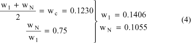
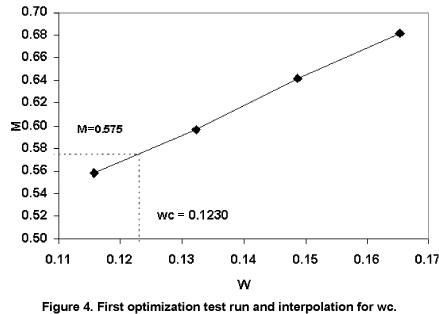
weight wc within its variation interval [w1,wN].
To obtain wc,
a first optimization test run was executed. Considering an arbitrary
weight parameter range discretized in N = 4 points, the fixed geometry
of the base airfoil was kept, with only M as a decision variable. The
results, presented in Fig. 4,
were then interpolated for M = 0.575, resulting in wc
= 0.1230. This value was then assumed to occur exactly at mid cruise
weight, so it is the average of the extreme values w1
and wN.
Considering the cruise weight fraction adopted (Eq. 2), a system of
equations defines the extreme weight values, as follows:


It
can be observed that, if a constant Mach number of M = Mref = 0.575 is
kept, the relation from Eq. 3 yields an expected CL
range [CL1,CLN], where:
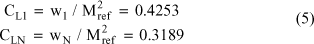

That cruise CL
range is closely compatible with those observed for typical jet
transport aircraft (Raymer, 1989). Once defined the weight parameter
interval [w1,wN] which is
mid divided by the best operation point wc
of the base airfoil, the optimization cases were set, representing two
possible combinations of decision variables involving variable LE and
TE camber parameters. Therefore, Case 1 (TE) includes only TE
displacements (dxTE and dzTE) and Case 2 (LE+TE) includes
LE and TE displacements (dxTE,
dzTE and dxLE, dzLE).
It is seen that, although the method is able to handle M as a variable, no such condition has been studied (other than the first test run, necessary to define wc). This has been decided because typical jet transport aircraft engines usually have specific fuel consumption factors C very sensitive to flight speed, and so the engines are expected to work within a tight M variation range, around an optimum consumption point. Once C has been previously assumed as a constant (Eq. 1), the inclusion of M variation has been considered useless and left for future research, when a model for C variation would eventually allow any C x M trade-off studies. Given that, the reference value M = 0.575 is always assumed. For all cases studied, the weight range was discretized into four equal segments, defining the five point interval [w1,w5] (N=5).
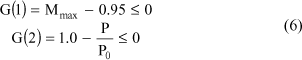
Finally, two constraints are imposed: (a) the
maximum local Mach number at any point over the airfoil surface Mmax
must never exceed 0.95 and (b) the total perimeter P of the airfoil
must never be less than 0.99 times that of the original base airfoil, P0.
These restrictions are put in terms of two functions submitted to
inequations:

Results and Discussion
Figures 5 to 17 present several results obtained for the two optimization cases run, which are compared to the base airfoil data, obtained under the same weight range and flow conditions described above. The data are discussed below, for each case separately.
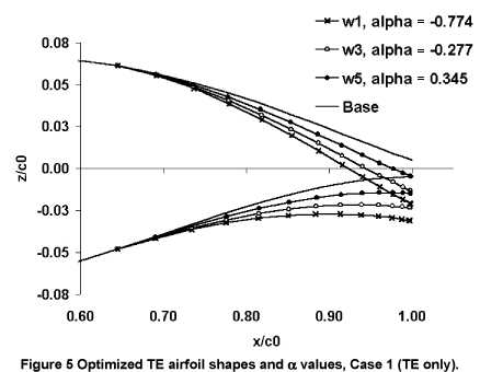

Case 1: Trailing edge variable camber:
The resulting TE variable camber shapes obtained for three of the five
weight values wi within the range defined (Eq.
4) are displayed in Fig. 5.
The gradual reduction of camber curvature from the highest weight w1
to the lowest w5 can be clearly observed, as
well as the a variation
needed to cope with the weight constraint (wi = M2CL).
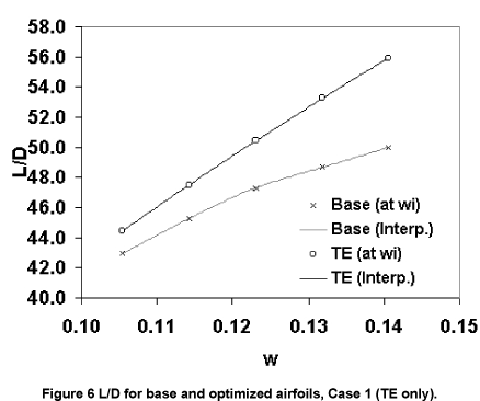
Fig. 6
gives an indication of the L/D increase obtained with the geometry
adaptation, in relation to the fixed airfoil. However, it is believed
that the variation of the integrand term of the range equation M(L/D)/w
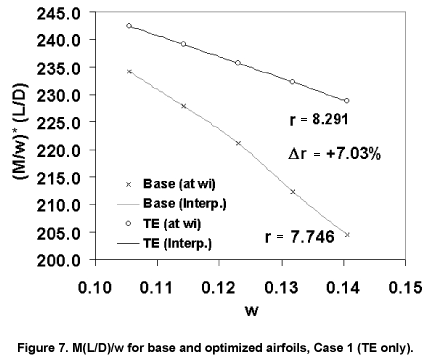
(Eq. 1) in Fig. 7 gives a
clearer indication of
what that efficiency increase means in terms of potential increase in
integrated range parameter r (area below each
curve). As indicated, an increase of Dr
= +7.03% is expectable.
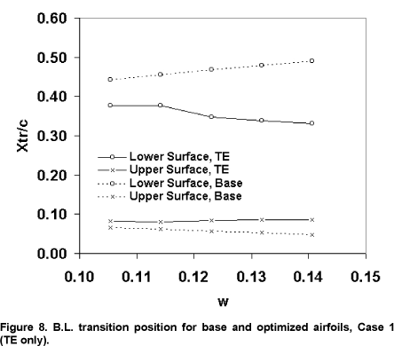
Figure 8
presents the estimated boundary layer transition position Xtr/c,
for both upper and lower surfaces of the adaptive TE and fixed base
airfoils. It is clear that the total (upper plus lower) extension of
laminar flow is reduced for every weight parameter. In contrast to the
increase in L/D observed (Fig. 5),
this result indicates that possibly a friction x pressure drag
trade-off has occurred.
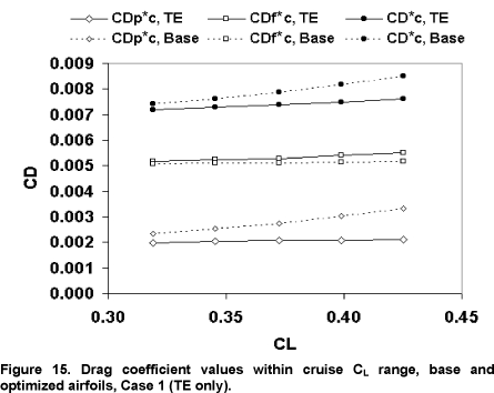
That trend is confirmed by the data from Fig.
15, which displays the
estimated values of pressure (CDp) and friction
(CDf) drag coefficients separately, as well as
their sum (CD = CDp + CDf),
all against the CL
values limiting the weight range (Eq. 5). The optimization clearly
indicates that, for the weight parameter range, base airfoil geometry
and flow conditions studied, it may be interesting to pay a small price
in friction drag, which may lead to a larger relative reduction in
pressure drag, thus minimizing total CD.
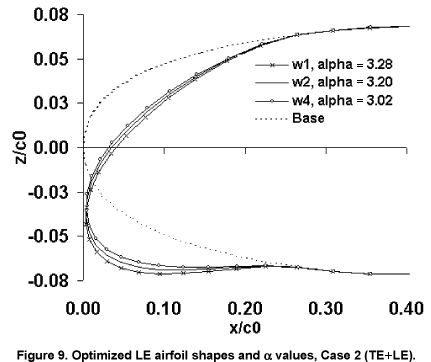
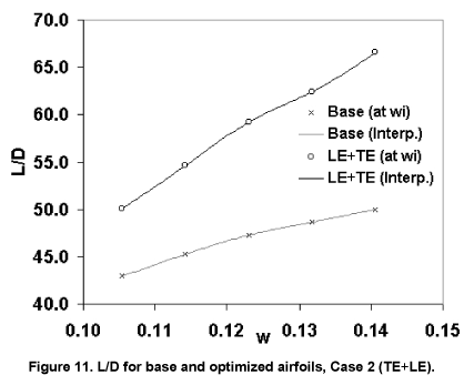
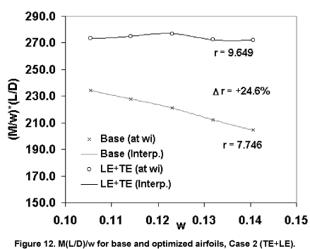
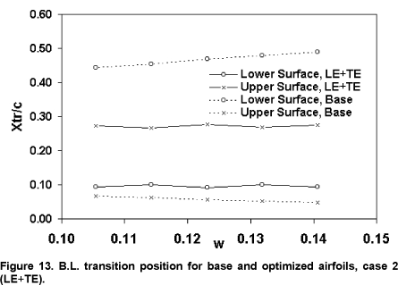
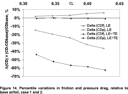
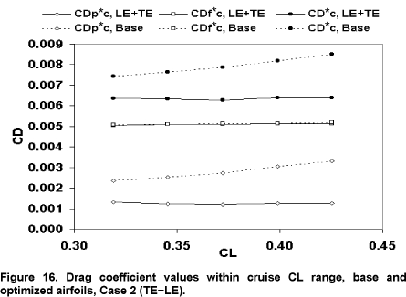
Case 2: Simultaneous trailing and leading edge variable camber: Fig. 9 and 10 present the resulting optimized geometries for the LE and TE simultaneously variable camber case, for three weight parameter values within the range [w1,w5]. The main feature evident in Fig. 9 is the intense downward curvature at the leading edge, probably adapting the stagnation point around it to an ideal position. Also, a gradual reduction of LE curvature with reduction of weight is clearly seen. Less obvious is the upward curvature of the trailing edge, displayed in Fig. 10, also gradually intensified by increasing weight. Fig. 11 presents the resulting L/D increase observed within [w1,w5], clearly superior to both the base airfoil and the previous case. The corresponding curves of the M(L/D)/w range parameter integrand are displayed in Fig. 12, indicating a variation Dr = 24.6% over the base airfoil, adding a 16.4% increase over Case 1. Fig. 13 indicates that the optimized configurations resulted in a total laminar boundary layer extents (Xtr/c) even shorter than that observed for Case 1 (Fig. 8), in spite of the large increases observed in L/D. Part of this effect is explained by a partial reduction of wetted area, within the 1% margin allowed by constraint G(2) (Eq. 6) and evident in Fig. 9. However, that result still favors the pressure x friction drag trade-off hypothesis, this time confirmed by Fig. 16. The CDp reduction reached is larger than that for Case 1, and CDf is also smaller, reaching values similar to those of the base airfoil. A comparison of those magnitudes is presented in Fig. 14, in terms of percentile drag variations relative to the base airfoil values (DCD = (CD-CDbase)/CDbase).
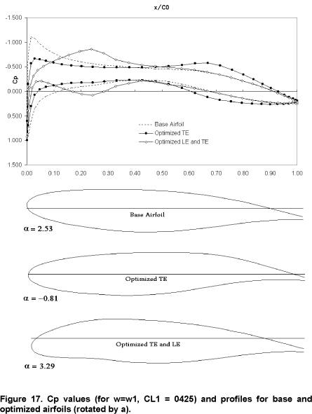
Pressure distributions: Results in terms of pressure distributions are displayed in Fig. 17, for the base airfoil and Case 1 and Case 2 optimized geometries, all for the highest loading condition of w = w1, CL = CL1 = 0.425. Along with the data there are profile representations (approximately to scale) of the reference airfoils, all of them rotated by a relative to the horizontal lines. One first interesting feature observed is the shape of the pressure distribution for the Case 2 airfoil, where LE adaptation smoothes down the upper surface suction peak seen on the base airfoil, bringing it to a more downstream position along the chord, thus largely alleviating the CP gradient after it. Apparently, the price paid for that is the appearance of a lower surface pressure peak at roughly the same chordwise position, and a resulting pressure gradient inversion that does not occur for the base airfoil, which explains the premature local BL transition (Fig. 13).
For the Case 1 airfoil, it is observed that a large suction peak reduction also occurs, although the unaltered LE curvature leaves it at roughly the same chordwise position. It can be seen that the Case 1 airfoil becomes "after-loaded", with the expected pressure difference increase around the curved TE.
Finally, an interesting and surprising "side effect" observation can be made: although taking only viscous drag considerations into account, the optimized result of Case 1 (TE only) tends to offer better transonic qualities than the base airfoil for the same condition. That is indicated in the flatter upper surface CP distribution that is generated in Case 1, which could possibly favor the formation of weaker shocks at higher Mach numbers. Comparing the base airfoil and the Case 1 optimized shape in Fig. 17, it can be seen that the latter has the LE of the airfoil at a much favorable angle of attack, offering its upper surface less deviated from the freestream. It is also evident that such behavior is coincidental, once the Case 2 (LE+TE) results depart from that trend, in spite of its greater number of optimization degrees of freedom. Such departure is also evident in Case 2 resulting shape and angle of attack (Fig. 17), which evidently demonstrates a trend to become a typically subcritical airfoil.
In summary, the observations made indicate that, under real supercritical cruise constraints, LE variable camber deflections are expected to be much less intense than the ones observed for Case 2.
Conclusions
Under the modeling simplifications and idealizations assumed, it is believed that the main objectives of this work were accomplished, allowing a first evaluation of the potential wing airfoil viscous drag reduction benefits reachable with the use of VCW technology, under typical jet transport operation conditions. Based on the results obtained and presented above, the following conclusions may be drawn:
(a) Within the limitations of the airfoil analysis method, it has been concluded that the idealized variable camber mechanism proposed would be able to considerably reduce wing airfoil viscous drag along the cruise leg of a typical jet transport aircraft. Translated into an integrated range parameter (Eq. 1) along the same weight variation interval, those reductions indicated a potential increase in range of 7.03% with the application of variable camber at the TE region only, a variation that increased to 24.6% when geometry adaptation was applied also to the LE region.
(b) The optimized geometry results (Fig. 5, 9 and 10) and the estimated potential range increases indicate that camber adaptation at the LE region is more significative for viscous drag reduction than at the TE. On the other hand, the results of the optimization of the TE region only (Case 1) coincidentally lead to pressure distributions much more favorable for transonic conditions, that is, with gradients close to zero along the upper surface (Fig. 16). Such coincidental confrontation of viscous drag and supercritical conditions indicates that probably much less LE curvature would be desirable at supercritical conditions, and introduces the question of whether it would be needed at all. This questioning is important when viewed from the standpoint of possibly easier mechanical implementation of the variable camber solution at the TE only, suggesting a future trade-off study.
(c) It has been observed that, at least for the
particular base airfoil adopted (Fig.2)
and for the conditions assumed, viscous drag reductions within the
cruise leg would occur entirely in terms of pressure drag. The friction
drag component for optimized VCW geometries was kept roughly the same
(Case 2, LE+TE) or even larger than (Case 1, LE) that of the base
airfoil, in favor of a pressure drag reduction of much larger
magnitude. It is recognized that the explanation of such results may
lie somewhere between reality, the limitations of the analysis method
and the choosing of the base airfoil (Fig
2) as
a representative typical one. Whatever is the case, the results suggest
the need for deeper future studies involving other base airfoils and
analysis methods.
Finally,
an important point that must be reminded about the results obtained is
the fact that, besides being limited by all the assumptions made, they
only take airfoil viscous drag considerations into
account,
analyzing its reduction without considering any trade-offs with other
sources of aerodynamic drag. However, the present results give some
indication of how much viscous drag reduction could
be achieved
under idealized conditions and typical operation conditions, thus
setting an upper limit to the expectations in that respect. Also, this
study demonstrates some evidence that supercritical flight conditions
would not allow the large LE deflections indicated for viscous drag
minimization, opening the question for a future trade-off study,
confronting viscous drag and supercritical conditions in a balance that
seems to be more sensitive than expected before.
References
Campanile, L. F. ; Hanselka, H., 1998a "A
Lightweight Concept for Aerodynamic Surfaces with Variable Camber".
ICAS-98-4,11,3, Melbourne, Australia. [ Links
]
Fielding,
J. P.; Varziry-Zanjany, M.A.F., 1996a,"Reliability, Maintainability and
Development Cost Implications of Variable Camber Wings". Aeronautical
Journal, May, p. 183-195. [ Links
]
Granville, P.S., 1953 "The Calculation of Viscous
Drag of Bodies of Revolution", David Taylor Model Basin, Report 849. [ Links
]
Gilyard,
G.; Espa±a, M., 1994, "On the Use of Controls for Subsonic
Transport Performance Improvement: Overview and Future Directions",
NASA TM 4605. [ Links
]
Horton, H.P, 1967 "A Semi-Empirical Theory for the
Growth and Bursting of Laminar Separation Bubbles", ARC CP 1073. [ Links
]
Martins,
A.L.; Catalano, F.M. 1998b, "Viscous Drag Optimization for a Transport
Aircraft Mission Adaptive Wing", ICAS-98-31499 Melbourne, Australia. [ Links
]
Martins,
A.L.; Catalano, F.M., 1996b, "Aerodynamic Optimization Study of a
Mission Adaptive Wing for Transport Aircraft", ICAS-96 Sorrento Italy.Links
]
McKinnon,
A.V., 1993, "An Experimental Study of a Variable Camber Wing", Ph.D.
Thesis, Cranfield Institute of Technology, UK, October. [ Links
]
Powers,
S.G.; Webb, L.D.,1997, "Flight Wing Surface Pressure Measurements and
Boundary-Layer Data from the F-111 Smooth Variable-Camber Supercritical
Mission Adaptive Wing", NASA TM 4789. [ Links
]
Raymer, D.P., 1989,"Aircraft Design: a Conceptual
Approach", AIAA Education Series. [ Links
]
Szodruch,
J., 1985, "The Influence of camber variation on the aerodynamics of
civil transport aircraft", AIAA 23th Aerospace Sciences Meeting, AIAA-
85-0353. [ Links
]
Torenbeek, E., 1982,"Synthesis of Subsonic Airplane
Design", Delft University Press. [ Links
]
Vanderplaats,
G. N., 1973, "CONMIN - A FORTRAN Program for Constrained Function
Minimization", NASA TM X-62282, Ames Research Center. [ Links
]
Williams,
B.R., 1984, " The Prediction of Separated Flow Using a Viscous-Inviscid
Iteration Method", R.A.E. Tech. Memo. Aero 2010. [ Links
]
Paper accepted September, 2002. Technical Editor:
Atila P.Silva Freire
[
® 2009 The Brazilian Society of
Mechanical Sciences and Engineering
Av. Rio
Branco, 124 - 14. Andar
20040-001 Rio de Janeiro RJ - Brazil
Tel.: +55 21 2221-0438
Fax: +55 21 2509-7129
