Blade Flyer
Remotely Controlled Model - Page 0
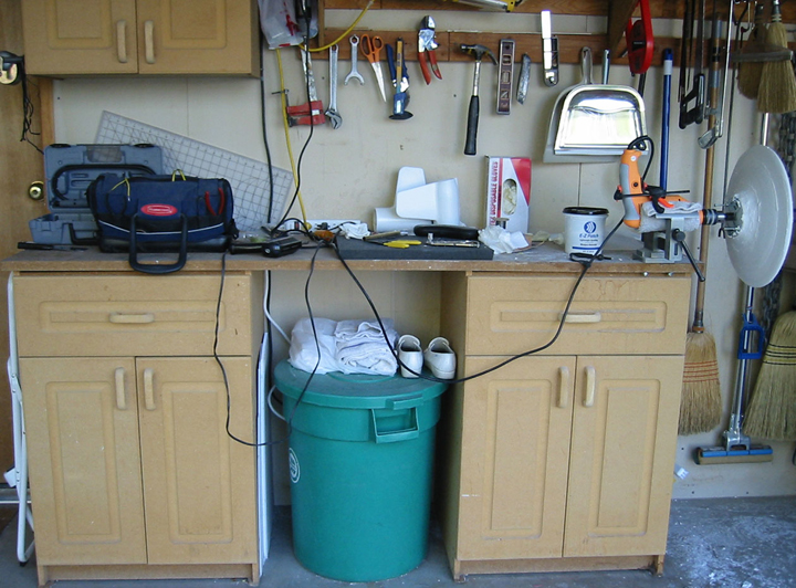
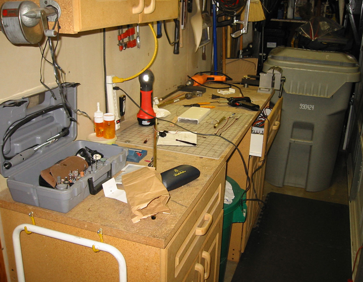
Limited work area.
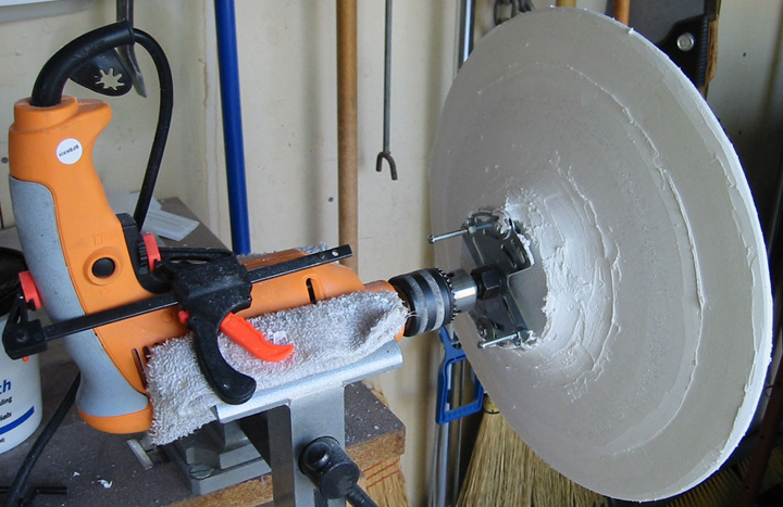
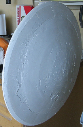
A hub made from laminated Styrofoam disks and plaster was more work than it was worth.
Turning it a drill was insufficiently consistent to guarantee symmetry. A stack of plastic plates will be used instead
The foam wings of a Guan Li A-10 RC model were made symmetric with filler and actuated, but the result was not robust enough to be appropriate. The wings were abandonded, but the transmiter, receiver, servos, engines, vertical stabilizers and horizontal stabilizers were used to create the RC Blade Flyer.
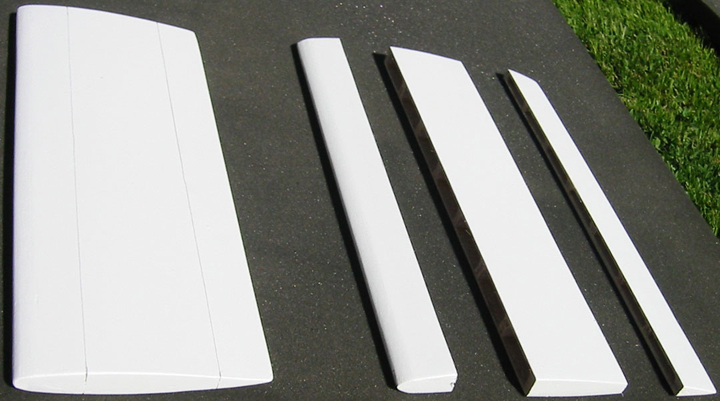
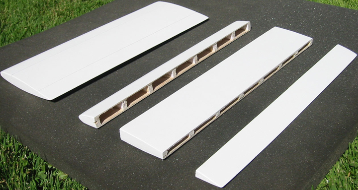
Blades fabricated from balsa wood, painted and cut into three pieces (slat, mid-body and flap):
The adjoining surfaces were notched to accommodate a set of 2" long 17/32" diameter brass tubes, which were glued in place with a 1/2" tube keeping them aligned to form a piano hinge for the slat. 9/32" diameter tubes were used for the flap.
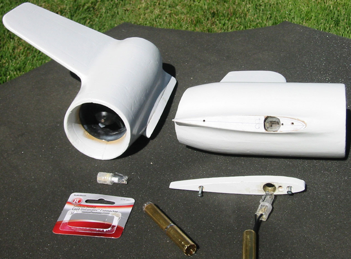
A-10 engines with A-10 vertical stabilizer adhered to the engine and faired. Two oak airfoil sections cut to math blade. One adhered to the engine over wires. A telephone connector soldered to the wires and placed in a hole in the airfoil section. The other airfoil section screws over the first, holding the telephone connector in place. This airfoil section has a 7/32" O.D. brass tube sleeve into which the 1/2" O.D. blade axle will fit. In the blade axle will be a telephone chord untangler, which will conduct power from the hub to the engine while allowing the engine to freely pivot on the axle. The connector was trimmed to the inside diameter of the axle tube with a cutter made from 1/2" tube with notches cut in one end and smaller tubes soldered into the other end to adequately support the cutter in a drill motor.
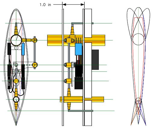
A commutator is used to communicate the servo commands from the transmitter to the servo. As the wing flips, the camber must reverse, so the commutator extends only half way around the shaft. When the wing flips a servo reverser connects with the commutator rather than connect with the direct connection with the servo, causing the camber to appropriately reverse.
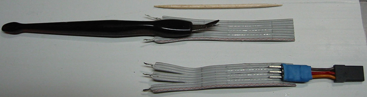
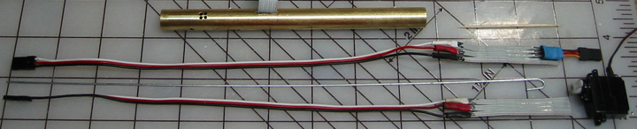
Parts of the insulation of a ribbon cable were cut away with a cuticle remover in order expose the wires to communicate a signal to a servo. Shown is a server reverser, which will be opposite a similar electrical assembly, so as the blade rotates on the axle, an up signal will have the same camber effect, regardless of the blade orientation.
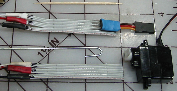
The connector of the commutator assembly will be slid through a slot in the axle tube, and the wire pulled through the tube with the hook shown until the ribbon cable is partially in the tube. The ribbon cable will be glued to the tube to form a commutator.
Commutator close-up with servo and servo reverser.
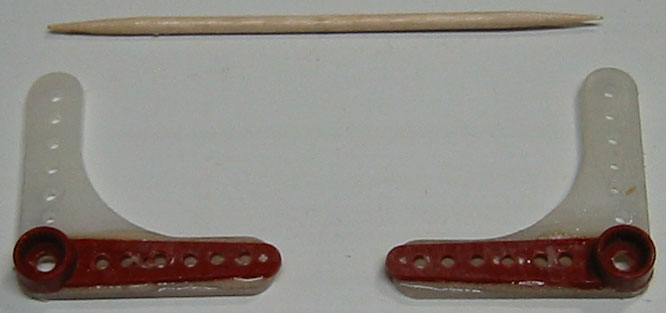
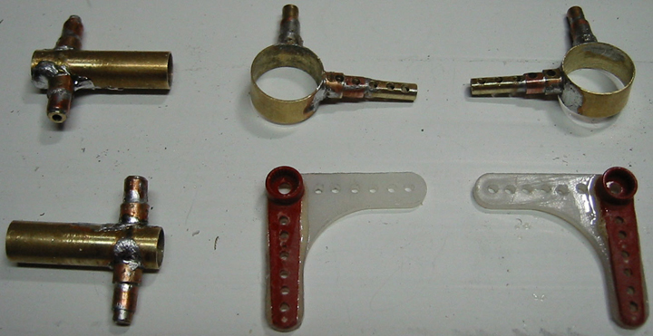
Modified control arms.
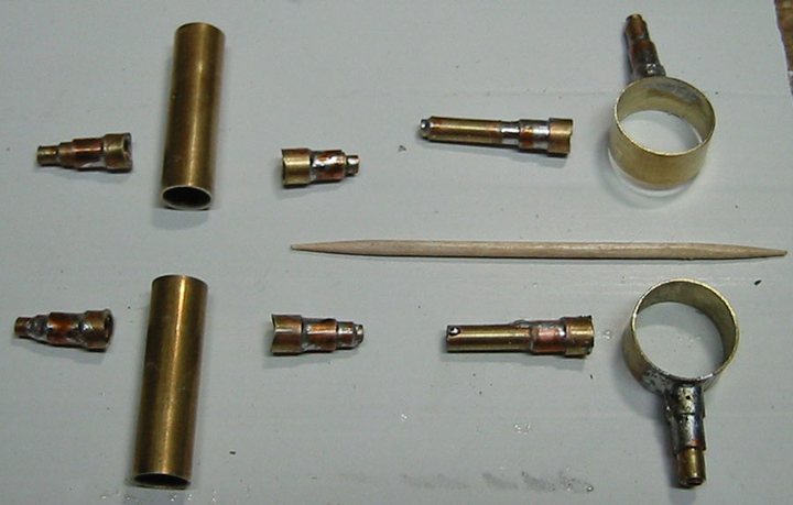
Actuator components fabricated from tubing.
Actuator parts assembled.
Quicktime Movie of blade assembled and actuation range adjusted until full 20-degree deflection is attained with both surfaces. Movement of the entire blade makes it appear as if the movement is not symmetric, but it is.
Winter workspace. I can't wait to finish the blade testing so I can disassemble the wind tunnel and have a heated workspace.
Contact: Bill Holmes via email or 661-305-9465
| Home | Wind Tunnel | Model 0 | Model 1 | Model 2 | Model 3 | Model 4 | Model 5 | Model 6 | Model 7 | Model 8 | Model 9 | Model 10 | Captive |