I
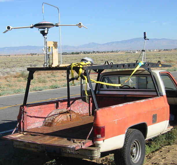
mounted the plywood base with its test sting and tripod to the top of
the rack of my brother-in-law's old pickup truck, and added another
piece of plywood to extend the test surface beyond the front of the
rack to avoid turbulence from the windshield. Driving to a
test
sight with the Blade Flyer in the back of my brother-in-law's old
pick-up truck has been counter-productive. The two times he
has
been off work from the LA County Fire Department and it was not windy,
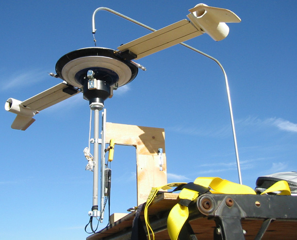
I've had to terminate the test after mounting the Blade Flyer on the
sting, a video camera on the tripod and connecting a safety harness, so
I can ride on the back of the truck to activate the Blade Flyer and
stabilize it after transition (the servo-released roller locked the
upper hub to the lower, but the vertical stabilizer was too small to
overcome the ring bearing resistance, so I removed the vertical).
I
terminated the first test, because I thought inconsistent camber
behavior was caused by bright sunlight interfering with the photo
detector. It turned out to be a loose receiver power
connector I
was touching when I covered the photo detector. I replaced the
connector.
I terminated the second test because engine thrust
was erratic. The internal receiver that controls the engines
and
roller release was shot, so I replaced it, but that did not solve the
problem. I could not isolate the problem to a
specific
circuit, so I re-soldered all the wires on the transmitter printed
circuit board (PCB) and the PCB between the battery, engines and
transmitter. When that didn't work, I removed all of the
electronics from the hub and installed all the transmitter PCB wires in
the PCB holes designed for them instead of soldering them to the face
of the pads on the reverse side as the manufacturer did to get it to
fit in its box.
That worked until I reinstalled the PCBs, pot,
switch, LCD PCB and receiver back in the hub. Maneuvering the
transmitter PCB into its mounts sorta fixed the problem. At
least
I can get full power from the engines.
Next time I'll follow the truck to the test site with the Blade Flyer
in my van.
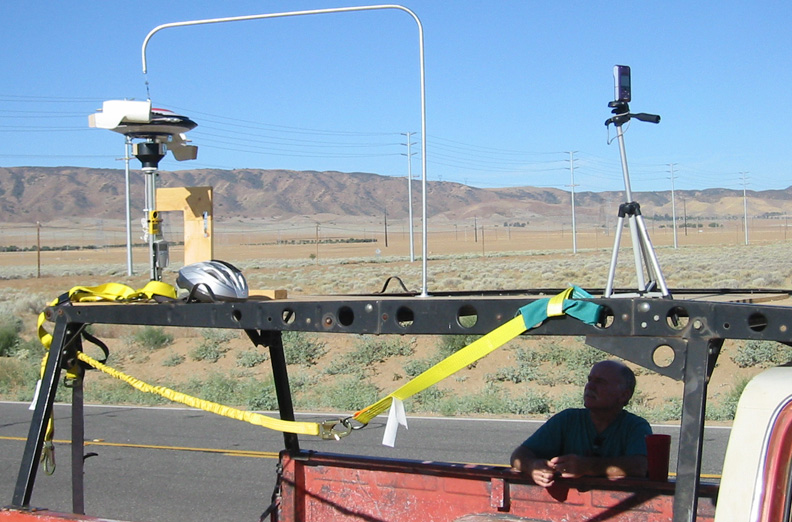
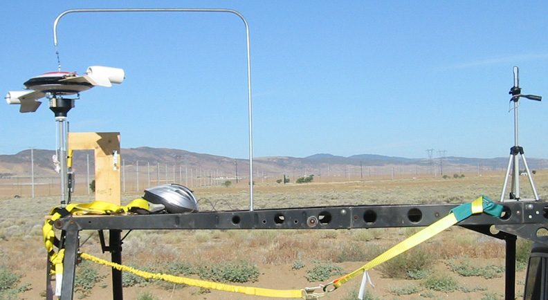
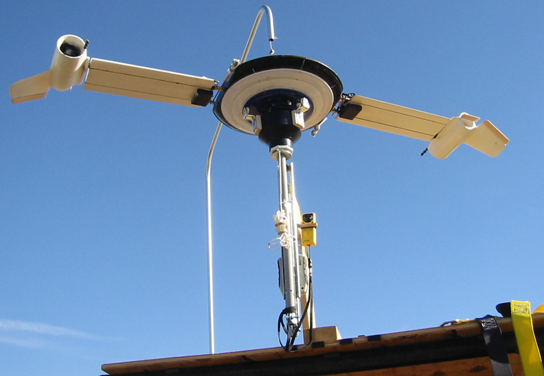
Third time is the charm on Monday, 2010 August 2, around 7 AM PST on
80th Street West,
north of Avenue K, Quartz Hill, California with the truck owner and
driver, Jim Swift, my brother-in-law. Plywood added to front to extend
base well over cab for smooth airflow.
Sony MHS-PM1 HD video camera on tripod. Safety strap and harness on
clearance from Lowe's for 75% off. My bike helmet. The sting,
instrumentation and safety support described in previous pages.
Field Test 1 - Neglected to un-weight scale when
enabling it and re-enabling it so it would display the total weight of the model and pedistal, but that
mattered little, because the wind speed and weight meters cannot be
seen well in the bright light.
Field Test 2 - Released model support, but blade
lift is
too little, actuator delay is too great, camber response amplitude is
too little, or some combination thereof to affect roll. Gimbal
installation was too tight to allow roll gimble to be rotated to
advance its actuation to compensate for system delay. Lost two weights
from one blade that balance the blade in pitch, so moved one to it from
the other blade.
Field Test 3 - Increased camber potentiometer.
Field Test 4 - Stopped configuration is good
except
retreating blade has too much friction and inertia to flip in
conjunction with its engine.
Field Test 5 - All transitions occurred at about 28 mph.
Spy Camera view
Field Test End Conclusions
The self-leveling intended by having the blades camber to
counter roll failed due to excessive vehicle mass, low blade lift,
control input lag or some combination thereof.
Blade lift-drag was insufficient to overcome blade axle friction.
Engines pivoted well using bearings and telephone chord untanglers as
commutators.
Even without split flaps on the trailing edges of the
vanes, the engine vanes demonstrated that the engines could be made to
rotate with the thrust vector down to compensate for retreating blade
lift loss.
$300 is insufficient for a model of the size and
sophistication needed to fully demonstrate no loss of lift during
transition.