Blade Flyer
Remotely Controlled Model - Page 8
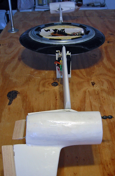
Disassembled the transmitter, and installed the
pitch-roll joystick at the center of the bottom of the vehicle, and the
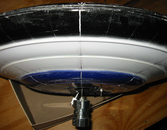
motor control and yaw control adjacent to it. Bolted pipe coupler to
the pitch-roll joystick.
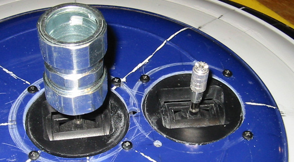
Moved the power switch to the side of the pitch-roll gimbal. Having the
weight of the entire vehicle supported on the joy stick is a major
concern. That's why the secondary support from the top.
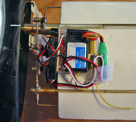
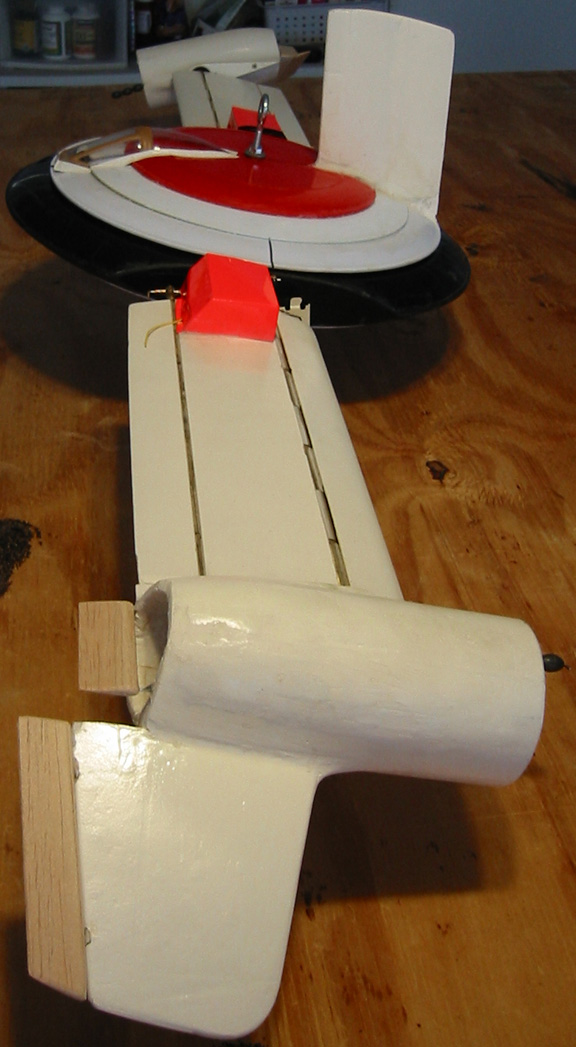
Moved the roller servo and receiver more to the aft.
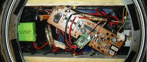
Installed the transmitter circuit board. Moved the
battery forward to balance the vehicle in pitch.
During the test, the power is enabled with the switch, and the
throttle is advanced to maximum. When the rotational velocity is high
enough for the roller counter-weight to keep the roller down, the yaw
control will be actuated with a stick to release the roller. The truck
accelerates until the translation velocity exceeds the rotation
velocity, and the engines and blades transition into the conventional
flight configuration. During the last few rotations, the roller weight
cause the roller to engage the slot in the top, so the vertical
stabilizer on the top stops the rotation, and maintains the vehicle
pointed into the translation air flow in conventional the flight
configuration.
Message to Dionysus
Design for later use here:
It
takes people a while to get their head around this concept. The
lifting surfaces are like helicopter blades during vertical flight and
wings during conventional flight.
INTRODUCTION
Google Air
Hogs Switchblade RC Plane to see a Canadian design that could be
construed to violate the Blade Flyer patent. It is a
symmetric
airfoil design that uses a spring to flip one blade relative to the
other once per flight. It must be manually reset. Its blades
are
directly connected to each other on a common axle. Its
engines
are fixed on each blade/wing.
The following text explains the photos and videos at BladeFlyer.com:
The
Blade Flyer is variable camber and uses translation air flow to flip
the blades into wings, so it automatically transitions between flight
modes as a function of its translation velocity. Each blade
is
independently connected to a common hub by way of an axle. The
engines are on the wing tips and freely pivot about their center of
gravity. For maximum efficiency, a vane on the engine keeps
the
engine pointed into the dominant air flow, regardless of whether it is
due to rotation or translation.
The engines begin flipping as
their translation air speed exceeds their rotation air speed. When the translation velocity of the retreating blade exceeds its
rotation speed, it flips. The engine and blade flipping slows
the
rotation to zero, and the vehicle achieves a conventional flight
configuration. A torque motor on the hub axle or a vertical
stabilizer on the hub engages to maintain the conventional flight
configuration. These are disengaged and the vehicle pitched
up or
otherwise slowed to reverse the process, and revert to vertical flight
configuration.
To avoid roll during transition, the dihedral on
the engine vane always causes the engine on the retreating blade to
flip with its thrust vector down to compensate for the reduced lift the
retreating blade relative to the advancing blade.
The blade/wing
airfoils are symmetric. Articulating leading and trailing
edges
provide camber to improve lift efficiency. A single servo in
each
blade actuates both the leading and trailing edges. Each
blade
has its own receiver and battery pack.
Each blade pivots on an
axle along the quarter chord (center of lift) of the blade. A
photo detector on each blade reflects its light off the blade
axle. Electrical tape on half of the circumference of the
axle
absorbs the light, and deactivates the photodetector as the blade
rotates about its axle. When again exposed to the shinny
brass of
the axle as the blade continues to rotate on the axle, the
photodetector reactivates.
By way of other circuitry, the
photodetector accordingly includes your servo reverser and glitch
reducer in the circuit between the receiver and servo, or excludes the
servo reverser and glitch reducer from the circuit between the receiver
and servo. This assures that the blade camber is always
producing
positive lift, regardless of the orientation of the blade (flipped or
not).
I need only demonstrate to DARPA that the Blade Flyer does
not lose lift during transition from vertical to conventional flight
mode and back. The wind tunnel I built for testing the
components
was under-sized to test the entire model, so I will mount the test
platform and model on a truck, drive it along our straight and flat
deserted desert roads, and video-tape a scale and the model during
translation at about 35 mph.
The model must be relatively free
to roll and demonstrate that it can maintain level flight during this
test, so I mounted the transmitter pitch-roll joystick gimbal inverted
in the center of the bottom of the hub. I secured the stick
to a
to bearing in a pedestal on the test stand such that a roll of the
model causes a roll command from the gimbal that increases the camber
on the low blade and decreases the camber on the high blade to correct
the roll of the vehicle during rotation in vertical flight mode or
during translation in conventional flight mode.
I mounted the
yaw-thrust joystick gimbal inverted in the bottom of the hub as
well. I mounted the transmitter, battery, engine control and
a
receiver in the middle of the hub. The engine control wires
thread through each axle, and connect to the male side of telephone
cable detangler in the end of the axle. The engine nacelles
mount
to bearings on the end of the axle such that the female side of the
telephone cable detangler in the nacelle connects to the male side to
provide power to the freely pivoting engines.
I mounted
the yaw servo in the middle of the hub such that it holds the axle of
the roller horizontal (in the plane of the hub) in counteraction to
weights on the other end of the roller axle, which pivots on a fulcrum
near its middle. The upper third of the hub freely rotates on
a
ring bearing such that its vertical stabilizer is free to orientate the
upper hub into the wind caused by translation. The upper hub
has
a rectangular slot in it that is slightly larger than the roller.
I
mounted a master switch in the bottom of the hub to interrupt the
circuit between the battery and the transmitter, yaw servo and engine
control, so the transmitter switch could be enabled and engine thrust
could be set before the test with the master switch off to preclude
anything from happening before I'm ready to start the test by enabling
the battery packs on each blade and the master switch on the hub.
The
blades and engines will be manually set in their vertical flight
orientation, and the engine thrust will be set to maximum before the
test.
Movement of the yaw stick by me in the back of the
truck with a pole after maximum rotation velocity is achieved will
release the weighted roller in the hub. Centrifugal force
will
keep the roller from engaging a slot in the upper hub. As the
rotation of the hub declines during transition, the roller will raise
to engage the slot in the top section of the hub. The
vertical
stabilizer on the top section of the hub will then stabilize the
vehicle in conventional flight mode.
YOU (Dionysus
Design)
The servos on
both blades must be signaled to cause some camber and some
corresponding lift to unweight the pedestal scale on the test stand
during vertical flight mode. I can do this with the pitch
potentiometer on the pitch-roll joystick by removing it from the
gimbal, and manually setting its position before the test.
The
servo on each blade must receive this fixed pitch signal as well as any
roll signal caused by the roll of the model on its pedestal. Hence the
pitch channel and roll channel on the receiver on each blade
must be mixed on its way to the photodetector circuit that supplies the
servo with its signal.
Is your V-Tail mixer appropriate for this purpose? If not,
what is?
Working mixers finally received and installed.
Adjusting battery position to nutralize pitch.
Covers for receiver and other electronics.
The
hub power switch and power LEDs cleared the original support, but a new
start-up support that clears the thrust and upper hub release joy stick
in its zero thrust position was required.
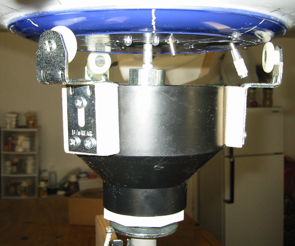
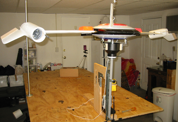
Safety support.
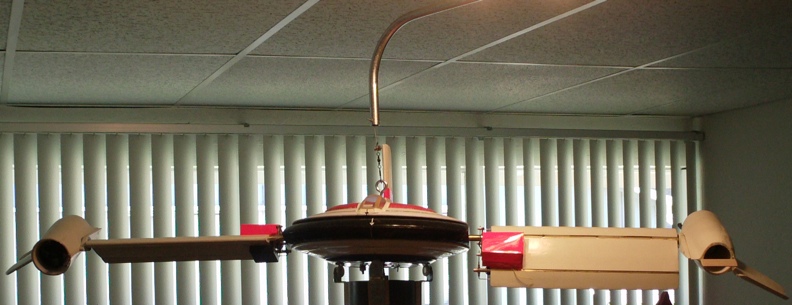
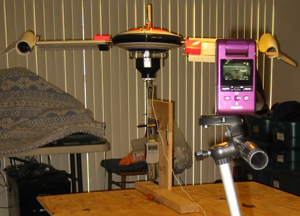
Full test assembly with model weight scale and air velocity meter on slide.
View from video camera showing support release string attached to pin in pedistal.
Contact: Bill Holmes via email or 661-305-9465
| Home
| Wind Tunnel | Model 0 | Model 1 | Model 2
| Model 3 | Model 4 | Model 5 | Model 6
| Model 7 | Model 8 | Model 9
| Model 10 | Captive |