Blade Flyer
Remotely Controlled Model - Page 10
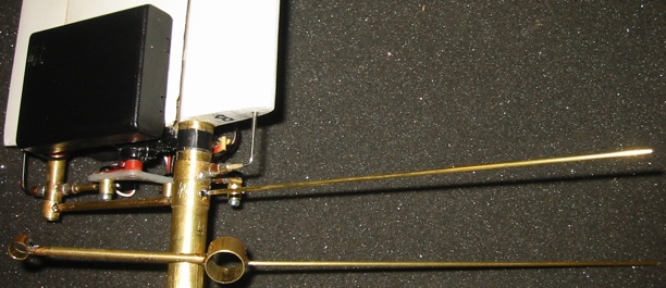
From brass tubing, I built a lever on which to place lead sinkers to counterbalance the weight of the wing/blade
To stiffen the lever, I added a copper tubing sleeve with the last of the intermediate brass tubing divided into four eighth inch pieces and solded in the ends fo the copper tube.
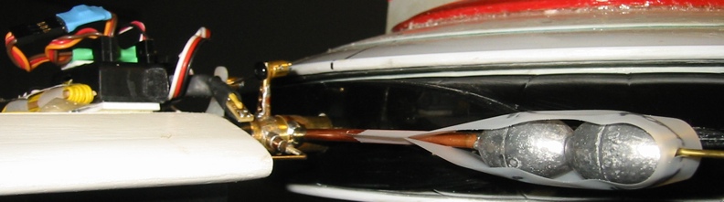
Assembled counter-balance with two 1.25 ounce sinkers.
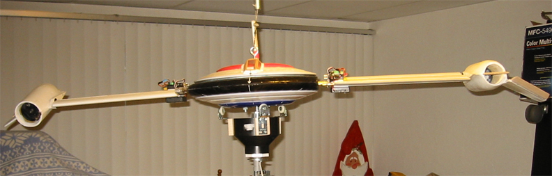
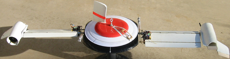
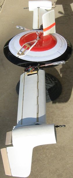
VTOL configuration.
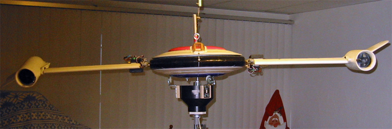
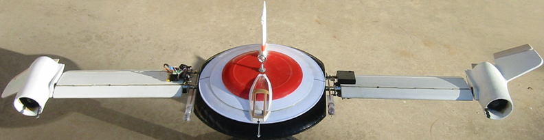
Conventional flight configuration.
Installed on the test sting, the pitch camber was adjusted and the roll response observed in both blades in VTOL and conventional flight configurations.
After three tests and engine thrust deflector adjustments and vane elevator adjustments to make the engine thrust axis parallel with the rotation plane, the model was allowed to achieve its maximum rotation velocity before the support was released. The blade lift was insufficient to keep the model level, or the response of the control system is too slow to compensate at the rotation speed, or both, so it slowly drifted to one side. Unfortunately, the scale was not reactivated, so any indication of net lift was not captured.
Given the inability of the model to maintain level flight, the road test will initially be conducted with the support in place to demonstrate transition. The resistance of the lazy susan bearing is too much for the vertical stabilizer to overcome, so the stabilizer will be removed.
VTOL configuration "front" view.
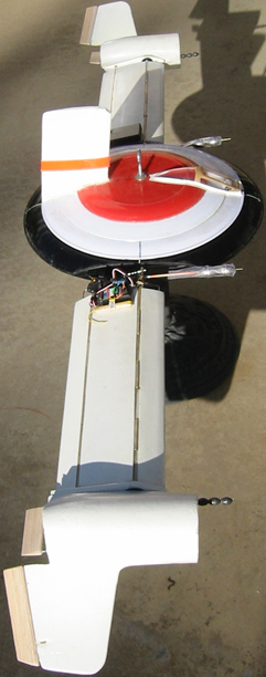
VTOL "side" view and Conventional configuration right side view.
Conventional configuration front view.
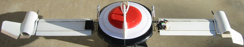
Conventional configuration back view.
Contact: Bill Holmes via email or 661-305-9465
| Home | Wind Tunnel | Model 0 | Model 1 | Model 2 | Model 3 | Model 4 | Model 5 | Model 6 | Model 7 | Model 8 | Model 9 | Model 10 | Captive |