Blade Flyer
Remotely Controlled Model - Page 5
Engines, flip, but inconsistently.
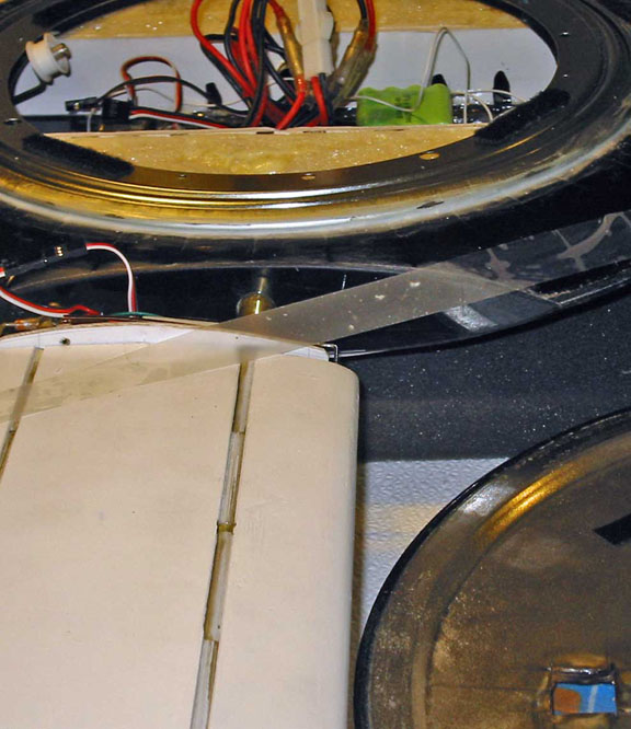
Added circlips (C-clips) to the base of the telephone chord untangles where they protrude from the blade axle, and increased the depth of the recess in the engine nacelles.
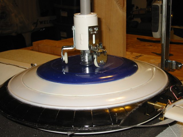
Noticed lose lower hub axle and discoverd the Gorilla Glue fatigued and failed after it thoroughly dried and became brittle, so rebuilt the hub, and substituted a 3 mm 0.5 screw in a dowel section in a grommet for the brass tube axle. The screw matches the RC transmitter gimbal arm, which will protrude through the bottom of the hub when it and the transmitter are mounted in the hub. Glued the aluminum gimble handle nut into a bearing, and mounted the bearing in a rigid conduit compression coupler that I attached to the end of a 0.5" PVC pipe.
Reamed a 1.25" PVC adapter in excess of the diameter of the PVC pipe, inserted it into a 1.25" coupler, and screwed screen door rollers to the coupler to provide a means of keeping the Blade Flyer level without landing gear until is achieves a rotational velocity sufficient to control its own orientation.
Modified and installed a 12" lazy susan bearing on the top of the lower hub to replace the upper brass tube bearing.
Cut a 4" diameter hole or larger through the lower hub plates.
Cut a slot in upper hub for hub locking wheel to enter when the hub rotations slows.
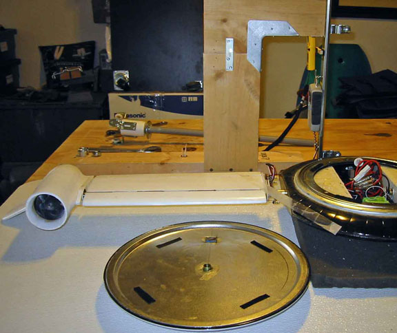
Built a mount from scrap 1x6" lumber, and attached a drawer slide to it.
Attached a digital fish scale to the slide to display the weight of the Blade Flyer.
Attached the air speed meter to an arm attached to the slide such that both displays can be seen from the left side with a video camera.
Contact: Bill Holmes via email or 661-305-9465
| Home | Wind Tunnel | Model 0 | Model 1 | Model 2 | Model 3 | Model 4 | Model 5 | Model 6 | Model 7 | Model 8 | Model 9 | Model 10 | Captive |