Blade Flyer
Remotely Controlled Model - Page 9
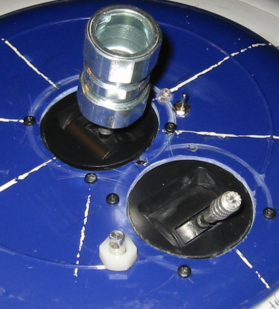
The pitch potentiometer in the pitch-roll gimbal was removed and installed in the bottom of the hub, and replaced with a dummy to hold the gimbal together.
The servos worked their way out of the blade during operation, so I added a a bracket to secure them in the blade.
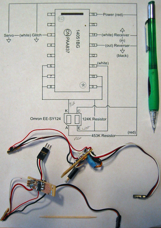
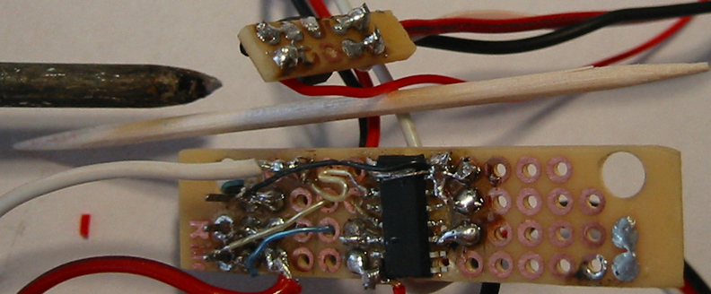
One photo dector circuit stopped working, so I rebuild both circuits to be more robust.
Working on surface mount components with conventional solder irons and prototype boards is difficult.
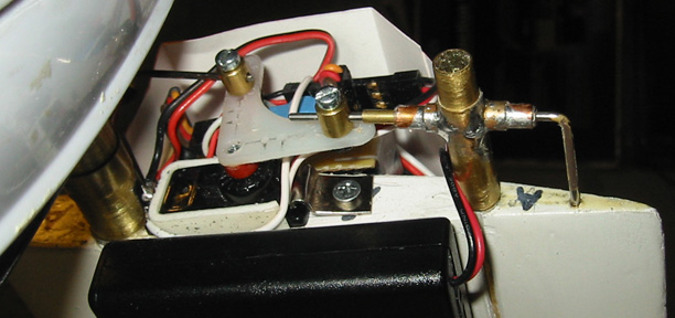
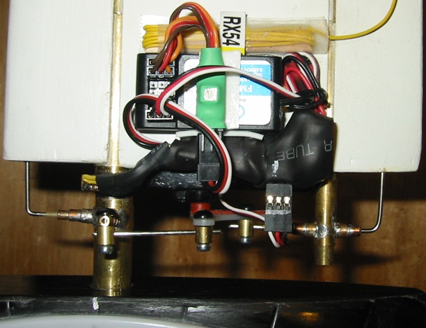
The B-Blade receiver with the green V-Tail Mixer on top and the photo dector-Servo Reverser circuit on the side is shown. I included a wire with the shrink tubing to provide a means of positioning the photo detector over the center of the blade axle. The shinny brass tubing apparently changed the frequency of the reflected light beyond the allowable range, so I wrapped the axle with a silvered mylar ribbon, and positioned a piece of black electrical tape around half of the axle to make the photo detector circuit work correctly.
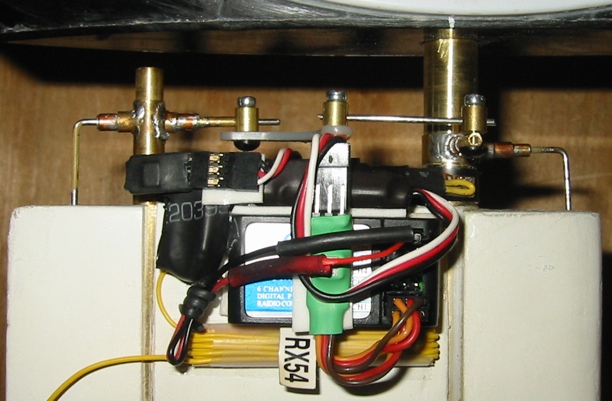
A-blade V-Tail Mixer, receiver and photo detector-servo reverser system.
The yellow wire is the receiver antenna.
Doinysus Design suggested an additional servo reverser on one channel of the blade that was not behaving as desired. That worked.
A rotation on the test fixture was insufficient to level the blades. Will have to counterbalance. The throttle gimbal is in the bottom of the hub, so I have to press it in as the model rotates. With the roller support dropped during the balance text, this will be easier. On the road test, I can use a stick to actuate the gimbal, but I may just let the batteries exhaust.
Contact: Bill Holmes via email or 661-305-9465
| Home | Wind Tunnel | Model 0 | Model 1 | Model 2 | Model 3 | Model 4 | Model 5 | Model 6 | Model 7 | Model 8 | Model 9 | Model 10 | Captive |