I built a wind tunned with a 30" x 14" test section for $80 after returns. I modified an A-10 model wing to be symmetric and include a slat. Control was marginal, so I extended slat and flap, added surface material to close gaps, and increased tunnel velocity to achieve successful camber control. It achieves a test section speed of 13 mph on low-speed and 26 mph on high-speed. Problems: concentric brass tubes used to allow the blade to freely rotate are not exactly round, so the rotational friction is inconsistent, and bearings are too viscous.
Based on that experience, I constructed a more robust blade from wood rather than adapt the other foam RC model wing to be symmetric. The current test blade has one servo for the flap and one for the slat. The new blade uses one servo for both with the ratio of deflection tuned to keep the center of lift at the quarter chord. A recent analysis indicates that the tunning need not be fine, because the center of lift is relatively stable during leading edge and trailing edge deflections.
After successful testing, an engine and vane will be attached to the blade, and tested in the tunnel to make sure it withstands the dynamic pressure, and consistently points into the air flow. After successful testing, a second blade-engine-vane assemble will be constructed, and both blades will be attached to a hub to complete the model.
The current test section is too small to accommodate the complete model. It was planned to double the wind tunnel width, but that would require exterior cabinets in which to store everything in the garage conversion that must be removed to accommodate a larger wind tunnel. Furthermore, air compressed between the test chamber top and bottom walls and the blades as they flip through transition will cause problems that can only be alleviated with an even larger tunnel.
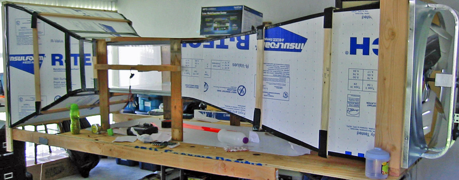 Left side of wind tunnel.
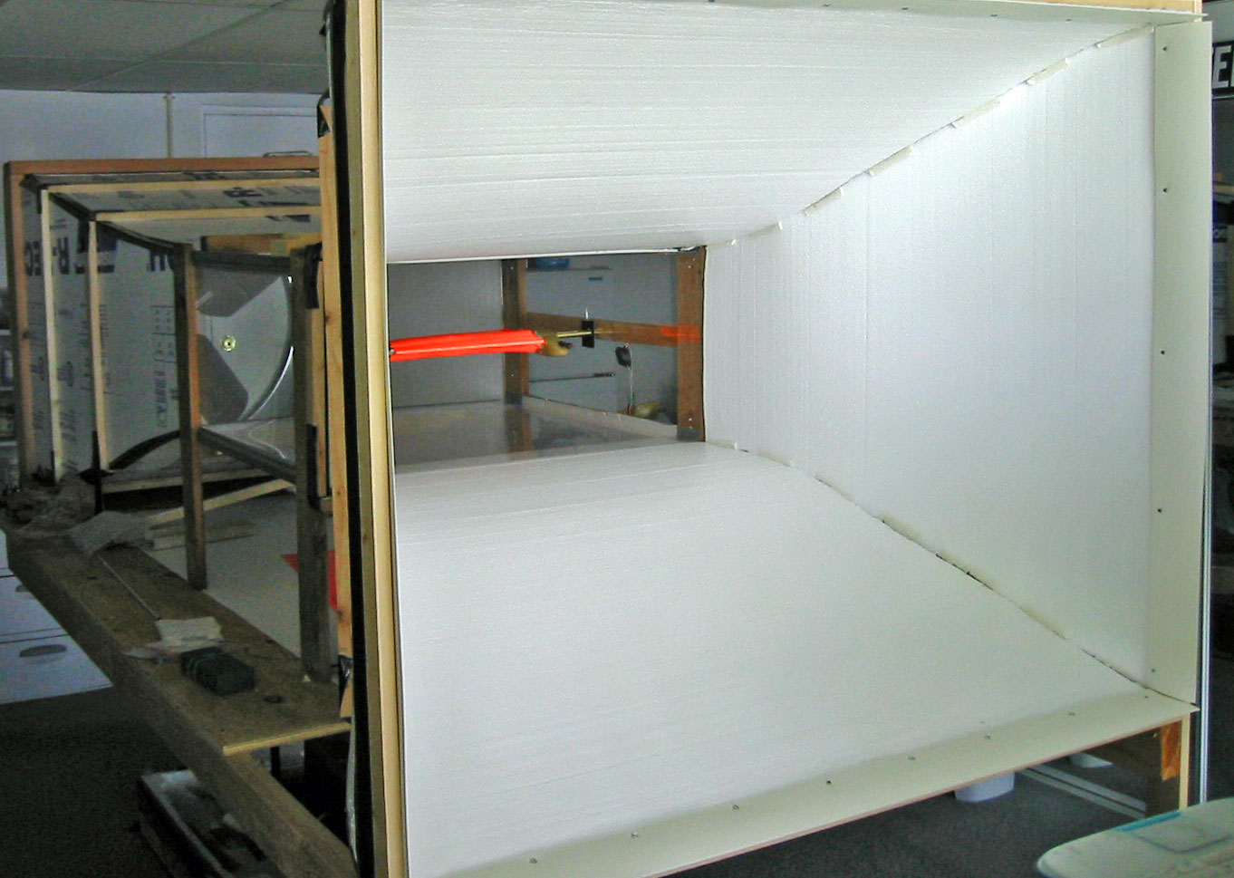 Inlet with extended wing in test section
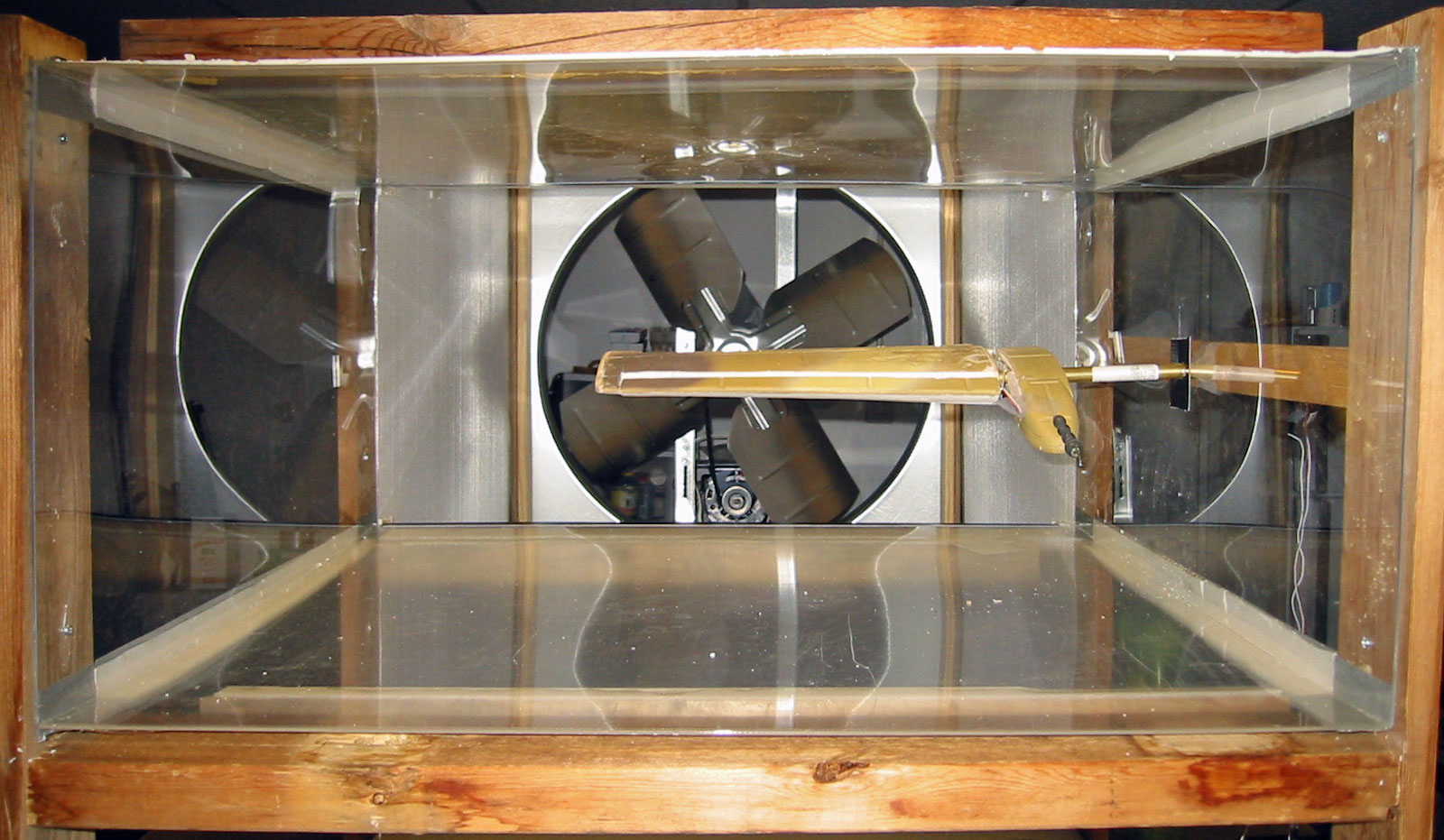
Original wing in test section with inlet removed.
The minimum cost to rent the Cal Tech tunnel is $20,000 for two days. Consequently, further tests will be conducted on a boom attached to the front of a vehicle driven on the remote and straight roads east of Lancaster.
The pitch and roll joystick unit will be removed from the control box. Its centering springs will be released, and it will be mounted on the boom. The Hub axle will be attached to the joystick such that the Blade Flyer is free to spin on the joy stick. The wires from the joy stick unit will be extended to the control box in the vehicle, so the trim and motor controls are accessible while traveling.As the the Blade Flyer pitches and rolls on the joy stick, the joy stick will command the blades as they rotate about the hub axle to camber to correct the movement and maintain level flight. This approach should continue to work as the blades flip in response to their transition velocity exceeding their rotational velocity. The trim control will effectively be the collective during vertical flight mode.
To avoid the complexity of split flaps on the vanes, a gravity will be used to engage the rotating upper part of the hub with a vertical stabilizer on it to the lower part of the hub as its rotation declines to stabilize the model in conventional flight mode.
A-Blade Test:
B-Blade Test
| Home | Wind Tunnel | Model 0 | Model 1 | Model 2 | Model 3 | Model 4 | Model 5 | Model 6 | Model 7 | Model 8 | Model 9 | Model 10 | Captive |